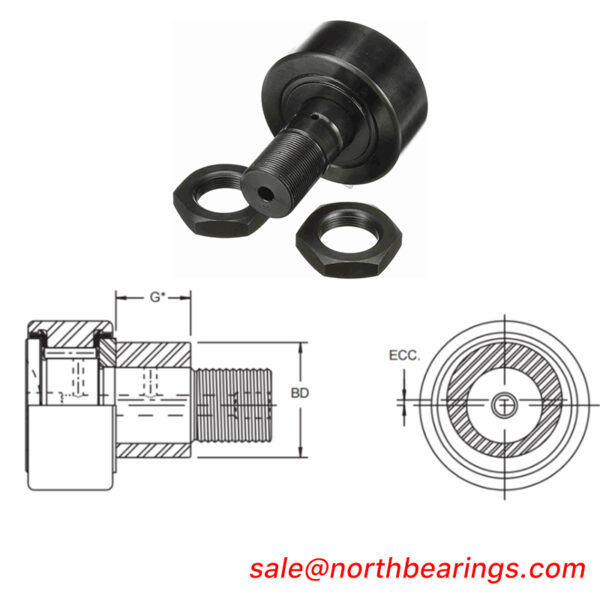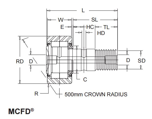

MCGILL MCFD-47,MCFD-52 METRIC CAMROL BEARINGS MCFD SERIES
MCGILL MCFD-47,MCFD-52 Description
| Â Â Â BEARING NO. | ROLLER DIA. RD (1) NOM. | ROLLER WIDTH W +0.00 -0.12 | Â STUD DIA. SD Â Â NOM. | STUD L’GTH. SL Â NOM. | OVERALL LENGTH L Â NOM. | ENDPLATE EXTENSION E Â NOM. | Â Â Â THREAD | THREAD LENGTH TL Â MIN. | Â OIL HOLE | REAMED HOLE D Â NOM. | |
| HC NOM. | HD NOM. | ||||||||||
| mm | mm | mm | mm | mm | mm | mm | mm | mm | mm | mm | |
| MCFD-35 | 35 | 18 | 16 | 32.5 | 52 | 0.8 | M16x1.5 | 17 | 8 | 3 | 6 |
| MCFD-40 | 40 | 20 | 18 | 36.5 | 58 | 0.8 | M18x1.5 | 19 | 8 | 3 | 6 |
| MCFD-47 | 47 | 24 | 20 | 40.5 | 66 | 0.8 | M20x1.5 | 21 | 9 | 4 | 8 |
| MCFD-52 | 52 | 24 | 20 | 40.5 | 66 | 0.8 | M20x1.5 | 21 | 9 | 4 | 8 |
| MCFD-62 | 62 | 29 | 24 | 49.5 | 80 | 0.8 | M24x1.5 | 25 | 11 | 4 | 8 |
| MCFD-72 | 72 | 29 | 24 | 49.5 | 80 | 0.8 | M24x1.5 | 25 | 11 | 4 | 8 |
| MCFD-80 | 80 | 35 | 30 | 63.0 | 100 | 1.0 | M30x1.5 | 32 | 15 | 4 | 8 |
| MCFD-90 | 90 | 35 | 30 | 63.0 | 100 | 1.0 | M30x1.5 | 32 | 15 | 4 | 8 |
| Â Â Â BEARING NO. | Â CORNER RADIUS R MIN. | Â Â ENDPLATE DIA. C | Â CLAMPING TORQUE (3) MAX. | LIMITING SPEED (2) | Â HOUSING BORE DIA. | Â LOAD RATING (NEWTONS) | Â Â BRG. MASS (APPROX.) | |||||
| GREASE | OIL | mm | ISO LOAD RATING | LOAD RATING AS TRACK ROLLER | ||||||||
| mm | mm | NOM. | rpm | rpm | MIN. | MAX. | DYNAMIC | STATIC | DYNAMIC | STATIC | Kg | |
| MCFD-35 | 0.6 | 21 | 57 | 6500 | 8500 | 16.000 | 16.018 | 23000 | 27000 | 16000 | 18000 | .165 |
| MCFD-40 | 1.0 | 23 | 85 | 5500 | 7200 | 18.000 | 18.018 | 25000 | 31000 | 18000 | 22000 | .242 |
| MCFD-47 | 1.0 | 27 | 118 | 4200 | 5500 | 20.000 | 20.021 | 38000 | 48000 | 27000 | 32000 | .380 |
| MCFD-52 | 1.0 | 21 | 118 | 3400 | 4400 | 20.000 | 20.021 | 42000 | 57000 | 30000 | 35000 | .450 |
| MCFD-62 | 1.0 | 38 | 216 | 2600 | 3400 | 24.000 | 24.021 | 58000 | 76000 | 41000 | 48000 | .795 |
| MCFD-72 | 1.1 | 44 | 216 | 2100 | 2700 | 24.000 | 24.021 | 64000 | 89000 | 46000 | 57000 | 1.010 |
| MCFD-80 | 1.1 | 47 | 441 | 1800 | 2300 | 30.000 | 30.021 | 94000 | 129000 | 67000 | 91000 | 1.540 |
| MCFD-90 | 1.1 | 47 | 441 | 1800 | 2300 | 30.000 | 30.021 | 94000 | 129000 | 67000 | 101000 | 1.960 |
STUD TYPE
Series MCFD® â?Shielded, full complement of cylindrical rollers

MCGILL MCFD-47,MCFD-52 Nots
Standard bearing has a crowned roller outside diameter. For straight cylindrical outside diameter, add suffix “X”. (Example – MCFD-35-X)
(2) Since load, lubrication method, temperature and other factors affect the maximum operating speed, it is impossible to determine precise limiting speed. The
listed limiting speeds are based on lightly loaded bearings having adequate lubrication and are listed only as a design guide. If grease lubricated, frequent
relubrication is required. Actual bearing testing in the specific application should be conducted if the anticipated operating speed approaches the listed limiting
speed.
(3) Clamping torque is based on dry threads. If threads are lubricated, use half of value shown
Tolerance limits for Cylindrical Roller Dia. “RD”
| RD (NOM.) | TOLERANCE | ||
| OVER | INCL. | MAX. | MIN. |
| mm | mm | mm | mm |
| 30 | 50 | 0 | -0.011 |
| 50 | 80 | 0 | -0.013 |
| 80 | 120 | 0 | -0.015 |
Tolerance limits for Crowned Roller Dia. “RD”
| RD (NOM.) | TOLERANCE | ||
| OVER | INCL. | MAX. | MIN. |
| mm | mm | mm | mm |
| 30 | 120 | 0 | -0.050 |
Tolerance limits for Stud Dia. “SD”
| SD (NOM.) | TOLERANCE | ||
| OVER | INCL. | MAX. | MIN. |
| mm | mm | mm | mm |
| 10 | 18 | 0 | -0.018 |
| 18 | 30 | 0 | -0.021 |

