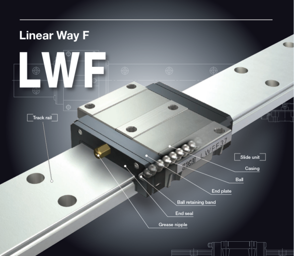

IKO LWFH 60 Linear Way F
IKO LWFH 60 Description
| Identification number | Interchangeable | Mass(Ref.) | Dimensions of assembly mm | Dimensions of slide unit
mm | Dimensions of track rail
mm | Appended mounting bolt for track rail(2) mm
Bolt size×R | Basic dynamic load rating(3)
C N | Basic static load rating(3)
C0 N | Static moment rating(3) | |||||||||||||||||||||||||
| LWF series (No C-Lube) | Slide unit kg | Track rail kg/m | H | H1 | N | W1 | W2 | W3 | W4 | L1 | L2 | L5 | d1 | M1×depth 1 | depth 2 | H2 | H3 | W | H4 | W5 | W6 | d3 | d4 | h | E | F | T0 N・m | TX N・m | TY N・m | |||||
| LWFH 40 | ○ | 0.58 | 4.60 | 27 | 5 | 21 | 91 | 82 | 37 | 4 | 70 | 60 | 27.5 | 4.3 | M 5×14 | 8 | 14 | 6.5 | 40 | 16 | 24 | 8 | 4.5 | 7.2 | 6 | 30 | 60 | M4×16 | 12 600 | 16 600 | 280 | 108 612 | 99.3 563 | |
| LWFH 60 | ○ | 1.29 | 8.60 | 35 | 6 | 25 | 119 | 110 | 47.5 | 7.5 | 90 | 75 | 45 | 6.7 | M 8×18 | 11 | 18 | 6.5 | 60 | 20 | 40 | 10 | 7 | 11 | 9 | 40 | 80 | M6×22 | 16 100 | 23 500 | 600 | 210 1 090 | 193 998 | |
| LWFH 90 | ○ | 4.06 | 16.5 | 50 | 7 | 36 | - | 162 | 72 | 9 | 120 | 100 | 60 | 8.6 | M10×20 | 20.5 | 26 | 12 | 90 | 25.5 | 60 | 15 | 9 | 14 | 12 | 40 | 80 | M8×28 | 31 600 | 43 300 | 1 650 | 513 2 680 | 470 2 460 | |

IKO LWFH 60 Nots
Notes (1) Track rail lengths L are shown in Table 2.1 on page Ⅱ-138.
(2) The appended track rail mounting bolts are hexagon socket head bolts equivalent to JIS B 1176. For size 40, small-head bolts are
appended.
(3) The direction of basic dynamic load rating (C), basic static load rating (C0), and static moment rating (T0, TX, TY) are shown in the
sketches below. The upper values of TX and TY are for one slide unit and the lower values are for two slide units in close contact.
Remark: The specifications of grease nipple are shown in Table 15 on page Ⅱ-146.
IKO LWFH 60 Example of identification number of assembled set


