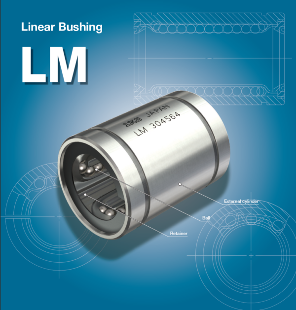

IKO LM 150210240* Linear Bushing
IKO LM 150210240* Description
|
Shaft diameter
mm | Identification number | Nominal dimensions and tolerances mm | Eccentricity
Maximum μm | Basic dynamic load rating C | Basic static load rating C0 | |||||||||||||||||||||||||||||||
| Standard type | Ball raceway | Mass (Ref.) g | Adjustable clearance type | Ball raceway | Mass (Ref.) g | Open type | Ball raceway | Mass (Ref.) g | ||||||||||||||||||||||||||||
| Dim. F w | C2 | D1 | h | E | α Degree | |||||||||||||||||||||||||||||||
| Fw | tolerance μm | D | Dim. D tolerance μm | C | Dim. C tolerance μm | C(1 1) | Dim. C1 tolerance μm | Load direction A N | Load direction B N | Load direction A N | Load direction B N | |||||||||||||||||||||||||
| P | H | P | H | |||||||||||||||||||||||||||||||||
| 60 | LM LM | 6090110 6090110 N | 6 6 | 1 817 1 787 | LM LM | 6090110 6090110 N | AJ* AJ* | 6 6 | 1 788 1 757 | LM LM | 6090110 6090110 N | OP* OP* | 5 5 | 1 650 1 610 | 60 | 0 — 9 | 0 -15 | 90 | 0 -22 | 110 | 0 -300 | 85 | 0 -300 | 3.15 | 86.5 | 3 | 30 | 50 | 17 | 25 | 4 760 | 5 040 | 8 150 | 10 400 | ||
| 80 | LM | 80120140* | 6 | 4 520 | LM | 80120140 | AJ* | 6 | 4 400 | LM | 80120140 | OP* | 5 | 3 750 | 80 | 120 | 140 | 105.5 | 4.15 | 116 | 3 | 40 | 50 | 8 710 | 9 220 | 14 500 | 18 500 | |||||||||
| 100 | LM | 100150175* | 6 | 8 600 | LM | 100150175 | AJ* | 6 | 8 540 | LM | 100150175 | OP* | 5 | 7 200 | 100 | 0 | 0 | 150 | 0 | 175 | 0 | 125.5 | 0 | 4.15 | 145 | 3 | 50 | 50 | 20 | 30 | 14 500 | 15 300 | 22 800 | 29 200 | ||
| -10 | -20 | -25 | -400 | -400 | ||||||||||||||||||||||||||||||||
| 120 | LM | 120180200* | 8 | 15 000 | LM | 120180200 | AJ* | 8 | 14 900 | LM | 120180200 | OP* | 6 | 11 600 | 120 | 180 | 200 | 158.6 | 4.15 | 175 | 3 | 85 | 80 | 25 800 | 25 500 | 44 300 | 49 400 | |||||||||
| 150 | LM | 150210240* | 8 | 20 250 | LM | 150210240 | AJ* | 8 | 20 150 | LM | 150210240 | OP* | 6 | 15 700 | 150 | 0 | 0 | 210 | 0 | 240 | 170.6 | 5.15 | 204 | 3 | 105 | 80 | 25 | 40 | 35 600 | 35 100 | 61 200 | 68 200 | ||||
| -13 | -25 | -29 | ||||||||||||||||||||||||||||||||||

IKO LM 150210240* Nots
Note (1) The width of hub for fixing with circlip should be the value obtained by subtracting a circlip width value times two from the C1
dimension.
Remarks 1. “P” and “H” in Dim. Fw tolerance and Eccentricity represent precision and high, respectively.
2. Standard type and adjustable clearance type (shaft diameter 60 mm) end plates are fixed with stop ring for holes.
3. The identification numbers with * are our semi-standard items.

