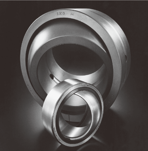

IKO GE 45EC-2RS,GE 50EC-2RS SPHERICAL BUSHINGS
IKO GE 45EC-2RS,GE 50EC-2RS Description
| Shaft dia.
mm | Identification number | Mass (Ref.)
kg | Boundary dimensions mm | Permissible tilting angle degree | ||||||||
| Without seals | With seals | d | D | B | C | dk | r (1) 1s min | r (1) 2s min | α | α1 | ||
| 15 | GE 15EC | ─ | 0.032 | 15 | 26 | 12 | 9 | 22 | 0.3 | 0.3 | 8 | ─ |
| 17 | GE 17EC | ─ | 0.049 | 17 | 30 | 14 | 10 | 25 | 0.3 | 0.3 | 10 | ─ |
| 20 | GE 20EC | ─ | 0.065 | 20 | 35 | 16 | 12 | 29 | 0.3 | 0.3 | 9 | ─ |
| 25 | GE 25EC | ─ | 0.115 | 25 | 42 | 20 | 16 | 35.5 | 0.6 | 0.6 | 7 | ─ |
| 30 | GE 30EC | GE 30EC-2RS | 0.160 | 30 | 47 | 22 | 18 | 40.7 | 0.6 | 0.6 | 6 | 4 |
| 35 | ─ | GE 35EC-2RS | 0.258 | 35 | 55 | 25 | 20 | 47 | 0.6 | 1 | ─ | 4 |
| 40 | ─ | GE 40EC-2RS | 0.315 | 40 | 62 | 28 | 22 | 53 | 0.6 | 1 | ─ | 4 |
| 45 | ─ | GE 45EC-2RS | 0.413 | 45 | 68 | 32 | 25 | 60 | 0.6 | 1 | ─ | 4 |
| 50 | ─ | GE 50EC-2RS | 0.560 | 50 | 75 | 35 | 28 | 66 | 0.6 | 1 | ─ | 4 |
| 60 | ─ | GE 60EC-2RS | 1.10 | 60 | 90 | 44 | 36 | 80 | 1 | 1 | ─ | 3 |
| 70 | ─ | GE 70EC-2RS | 1.54 | 70 | 105 | 49 | 40 | 92 | 1 | 1 | ─ | 4 |
| Mounting dimensions mm | Dynamic load capacity Cd N | Static load capacity Cs N | |||
| da | Da | ||||
| Min. | Max.(2) | Max. | Min. | ||
| 17.5 | 18 | 23.5 | 21.5 | 19 400 | 48 500 |
| 19.5 | 20.5 | 27.5 | 24.5 | 24 500 | 61 300 |
| 22.5 | 24 | 32.5 | 28 | 34 100 | 85 300 |
| 29 | 29 | 37.5 | 34 | 55 700 | 139 000 |
| 34 | 34 | 42.5 | 41.5 | 71 800 | 180 000 |
| 39.5 | 39.5 | 49.5 | 48 | 92 200 | 230 000 |
| 44.5 | 45 | 56.5 | 54.5 | 114 000 | 286 000 |
| 49.5 | 50.5 | 62.5 | 60 | 147 000 | 368 000 |
| 54.5 | 56 | 69.5 | 66 | 181 000 | 453 000 |
| 65.5 | 66.5 | 84.5 | 79 | 282 000 | 706 000 |
| 75.5 | 77.5 | 99.5 | 91 | 361 000 | 902 000 |

IKO GE 45EC-2RS,GE 50EC-2RS Nots
Notes(1) Minimum allowable value of chamfer dimensions r1 and r2
(2) When Spherical Bushings are used with full tilting angle, the shaft shoulder dimension must be less than the maximum value of da.
Remark No oil hole is provided.

