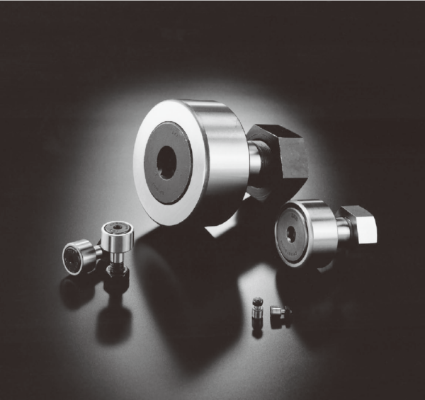

IKO CFE 10 VBR,CFE 10 VB CAM FOLLOWERS
IKO CFE 10 VBR,CFE 10 VB Description
| Outside diameter of eccentric collar mm | Identification number | Mass (Ref.) | ||||||
| Shield type | Sealed type | g | D | C | de | |||
| With crowned outer ring | With cylindrical outer ring | With crowned outer ring | With cylindrical outer ring | |||||
| 9 | CFE 6 VBR | CFE 6 VB | CFE 6 VBUUR | CFE 6 VBUU | 21 | 16 | 11 | 9 |
| 11 | CFE 8 VBR | CFE 8 VB | CFE 8 VBUUR | CFE 8 VBUU | 32.5 | 19 | 11 | 11 |
| 13 | CFE 10 VBR | CFE 10 VB | CFE 10 VBUUR | CFE 10 VBUU | 50.5 | 22 | 12 | 13 |
| CFE 10-1 VBR | CFE 10-1 VB | CFE 10-1 VBUUR | CFE 10-1 VBUU | 66 | 26 | 12 | 13 | |
| 16 | CFE 12 VBR | CFE 12 VB | CFE 12 VBUUR | CFE 12 VBUU | 107 | 30 | 14 | 16 |
| CFE 12-1 VBR | CFE 12-1 VB | CFE 12-1 VBUUR | CFE 12-1 VBUU | 117 | 32 | 14 | 16 | |
| 22 | CFE 16 VBR | CFE 16 VB | CFE 16 VBUUR | CFE 16 VBUU | 193 | 35 | 18 | 22 |
| 24 | CFE 18 VBR | CFE 18 VB | CFE 18 VBUUR | CFE 18 VBUU | 285 | 40 | 20 | 24 |
| 27 | CFE 20 VBR | CFE 20 VB | CFE 20 VBUUR | CFE 20 VBUU | 505 | 52 | 24 | 27 |
| CFE 20-1 VBR | CFE 20-1 VB | CFE 20-1 VBUUR | CFE 20-1 VBUU | 430 | 47 | 24 | 27 | |
| 33 | CFE 24 VBR | CFE 24 VB | CFE 24 VBUUR | CFE 24 VBUU | 900 | 62 | 29 | 33 |
| CFE 24-1 VBR | CFE 24-1 VB | CFE 24-1 VBUUR | CFE 24-1 VBUU | 1 220 | 72 | 29 | 33 | |
| CFE 30 VBR | CFE 30 VB | CFE 30 VBUUR | CFE 30 VBUU | 2 030 | 80 | 35 | 41 | |
| 41 | CFE 30-1 VBR CFE 30-2 VBR | CFE 30-1 VB CFE 30-2 VB | CFE 30-1 VBUUR CFE 30-2 VBUUR | CFE 30-1 VBUU CFE 30-2 VBUU | 2 190 2 380 | 85 90 | 35 35 | 41 41 |
| Boundary dimensions | mm | Mounting dimension f Min. mm | Maximum tightening torque
N-m | Basic dynamic load rating C
N | Basic static load rating C0 N | Maximum allowable static load
N | ||||||||||
|
e | ||||||||||||||||
| G | B3 | B max | B1 max | B2 | C1 | g1 | G1 | H | (1) rs min | |||||||
| M 6×1 | 7.5 | 12.2 | 28.2 | 16 | 0.6 | ─ | 8.5 | 3 | 0.3 | 0.4 | 11 | 2.7 | 6 980 | 8 500 | 1 950 | |
| M 8×1.25 | 9.5 | 12.2 | 32.2 | 20 | 0.6 | ─ | 10.5 | 4 | 0.3 | 0.4 | 13 | 6.5 | 8 170 | 11 200 | 4 620 | |
| M10×1.25 | 10.5 | 13.2 | 36.2 | 23 | 0.6 | ─ | 12.5 | 4 | 0.3 | 0.4 | 16 | 13.8 | 9 570 | 14 500 | 8 650 | |
| M10×1.25 | 10.5 | 13.2 | 36.2 | 23 | 0.6 | ─ | 12.5 | 4 | 0.3 | 0.4 | 16 | 13.8 | 9 570 | 14 500 | 8 650 | |
| M12×1.5 | 11.5 | 15.2 | 40.2 | 25 | 0.6 | 4 | 13.5 | 6 | 0.6 | 0.8 | 21 | 21.9 | 13 500 | 19 700 | 13 200 | |
| M12×1.5 | 11.5 | 15.2 | 40.2 | 25 | 0.6 | 4 | 13.5 | 6 | 0.6 | 0.8 | 21 | 21.9 | 13 500 | 19 700 | 13 200 | |
| M16×1.5 | 15.5 | 19.6 | 52.1 | 32.5 | 0.8 | 4 | 17 | 6 | 0.6 | 0.8 | 26 | 58.5 | 20 700 | 37 600 | 23 200 | |
| M18×1.5 | 17.5 | 21.6 | 58.1 | 36.5 | 0.8 | 6 | 19 | 8 | 1 | 0.8 | 29 | 86.2 | 25 300 | 51 300 | 31 100 | |
| M20×1.5 | 19.5 | 25.6 | 66.1 | 40.5 | 0.8 | 6 | 21 | 8 | 1 | 0.8 | 34 | 119 | 33 200 | 64 500 | 37 500 | |
| M20×1.5 | 19.5 | 25.6 | 66.1 | 40.5 | 0.8 | 6 | 21 | 8 | 1 | 0.8 | 34 | 119 | 33 200 | 64 500 | 37 500 | |
| M24×1.5 M24×1.5 | 25.5 25.5 | 30.6 30.6 | 80.1 80.1 | 49.5 49.5 | 0.8 0.8 | 6 6 | 24 24 | 12 12 | 1 1 | 0.8 0.8 | 40 40 | 215 215 | 46 600 46 600 | 92 000 92 000 | 52 000 52 000 | |
| M30×1.5 M30×1.5 | 32.5 32.5 | 37 37 | 100 100 | 63 63 | 1 1 | 6 6 | 30.5 30.5 | 17 17 | 1 1 | 1.5 1.5 | 49 49 | 438 438 | 67 700 67 700 | 144 000 144 000 | 85 900 85 900 | |
| M30×1.5 | 32.5 | 37 | 100 | 63 | 1 | 6 | 30.5 | 17 | 1 | 1.5 | 49 | 438 | 67 700 | 144 000 | 85 900 | |

IKO CFE 10 VBR,CFE 10 VB Nots
Note(1) Minimum allowable value of chamfer dimension r
Remarks1. Models with a stud diameter d1 of 4 mm or less have no oil hole. For models with a stud dia. 5 to 10mm, oil hole (re-greasing
fitting) is provided at the head. Other models are provided with an oil hole (grease nipple) at the head and an oil hole each on the
outside surface and end surface of the stud.
2. Shield type models with a stud diameter d1 of 10mm or less and the sealed type models are provided with prepacked grease.
Other models are not provided with prepacked grease. Perform proper lubrication for use.

