
IKO MXSG 55 C-Lube Linear Roller Way Super MX
IKO MXSG 55 Description
| Identification number | Interchangeable | Mass (Ref.) | Dimensions of assembly mm | Dimensions of slide unit mm | Dimensions of track rail mm | Mounting bolt for track rail(2)
Bolt size×R | Basic dynamic load rating(3)
C N | Basic static load rating(3)
C0 N | Static moment rating(3) | ||||||||||||||||||||||
| MX series | LRX series (No C-Lube) | Slide unit kg | Track rail kg/m | H | H1 | N | W1 | W2 | W3 | W4 | L1 | L2 | L3 | L5 | M1× depth | H3 | W | H4 | d3 | d4 | h | E | F | T0 N・m | TX N・m | TY N・m | |||||
| MXS 35 | - | ○ | 1.22 | 6.88 | 48 | 6.5 | 18 | 78 | 70 | 25 | 10 | 124 | 50 | 78.6 | 12.7 | M 8×12 | 13 | 34 | 32 | 9 | 14 | 12 | 40 | 80 | M 8×35 | 58 700 | 100 000 | 2 170 | 1 360 8 470 | 1 360 8 470 | |
| MXSG 35 | - | ○ | 1.61 | 152 | 72 | 106.6 | 74 200 | 135 000 | 2 930 | 2 440 13 800 | 2 440 13 800 | ||||||||||||||||||||
| MXS 45 | - | ○ | 2.37 | 10.8 | 60 | 8 | 20.5 | 96 | 86 | 30 | 13 | 154 | 60 | 99 | 17.5 | M10×18 | 16 | 45 | 38 | 14 | 20 | 17 | 52.5 | 105 | M12×40 | 95 400 | 159 000 | 4 430 | 2 700 16 800 | 2 700 16 800 | |
| MXSG 45 | - | ○ | 3.27 | 194 | 80 | 139 | 124 000 | 223 000 | 6 200 | 5 220 29 000 | 5 220 29 000 | ||||||||||||||||||||
| MXS 55 | - | ○ | 3.96 | 14.1 | 70 | 9 | 23.5 | 110 | 100 | 37.5 | 12.5 | 184 | 75 | 120 | 20 | M12×20 | 16 | 53 | 43 | 16 | 23 | 20 | 60 | 120 | M14×45 | 148 000 | 248 000 | 8 040 | 5 040 31 100 | 5 040 31 100 | |
| MXSG 55 | - | ○ | 5.63 | 238 | 95 | 174 | 198 000 | 359 000 | 11 700 | 10 400 57 000 | 10 400 57 000 | ||||||||||||||||||||

IKO MXSG 55 Nots
Notes (1) Track rail lengths L are shown in Table 2.1 on page Ⅱ-175 and Table 2.3 on page Ⅱ-176 .
(2) Track rail mounting bolts are not appended.
(3) The direction of basic dynamic load rating (C), basic static load rating (C0), and static moment rating (T0, TX, TY) are shown in the
sketches below. The upper values of TX and TY are for one slide unit and the lower values are for two slide units in close contact.
(4) The shapes of grease nipple vary by size. The specifications are shown in Table 15 on page Ⅱ-188.
Remark: Three grease nipple mounting thread holes are provided on the right and left end plates respectively.
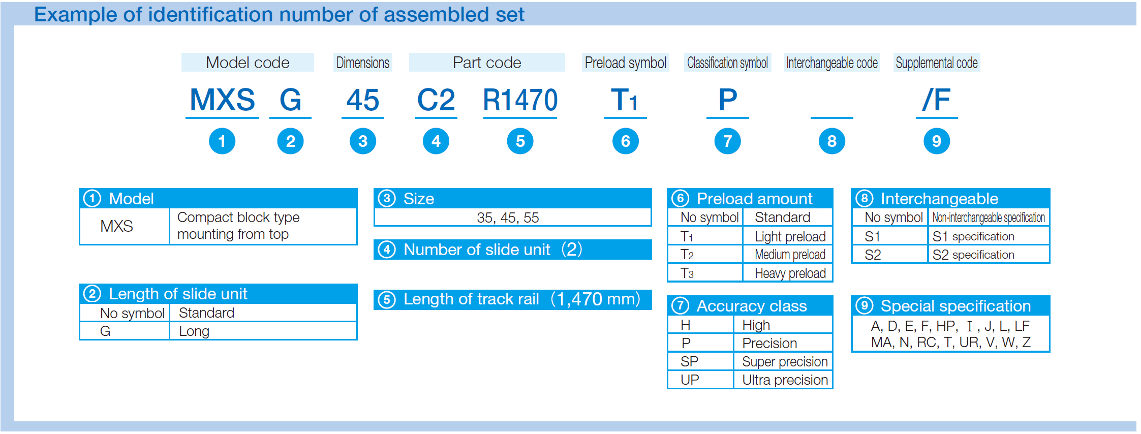
IKO MXSG 55 Example of identification number of assembled set


